European accelerated-computing systems

GRIFO 32.A larger machine.

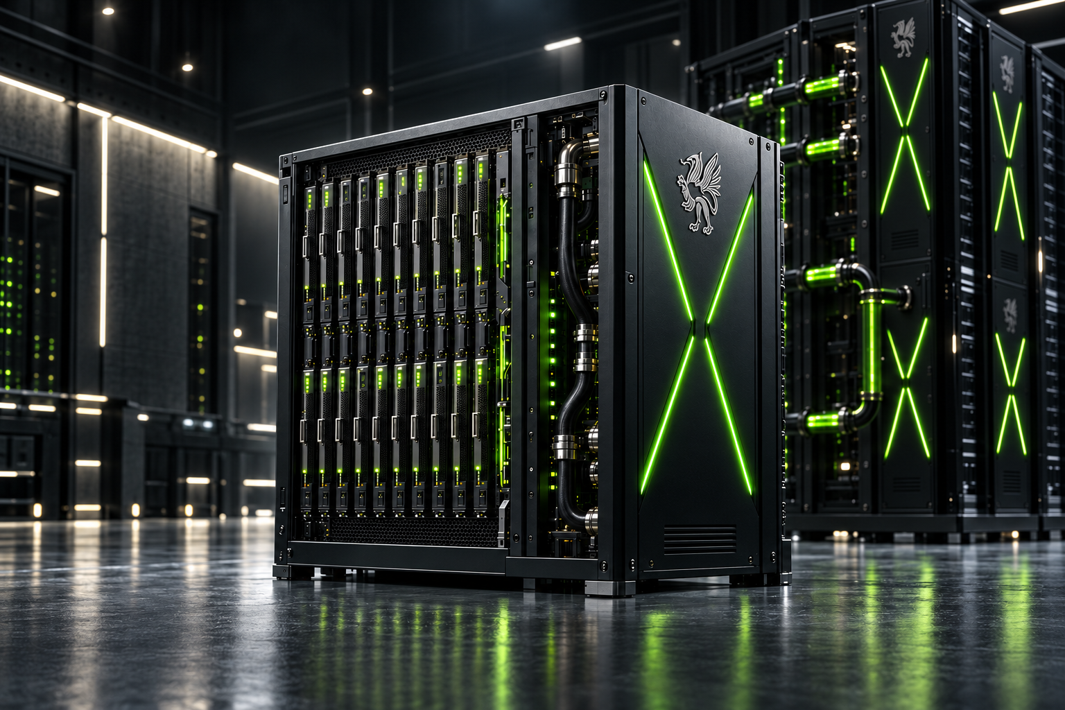
Billi Dynamics designs GRIFO systems to keep more accelerators, data movement and control inside one coordinated local architecture.

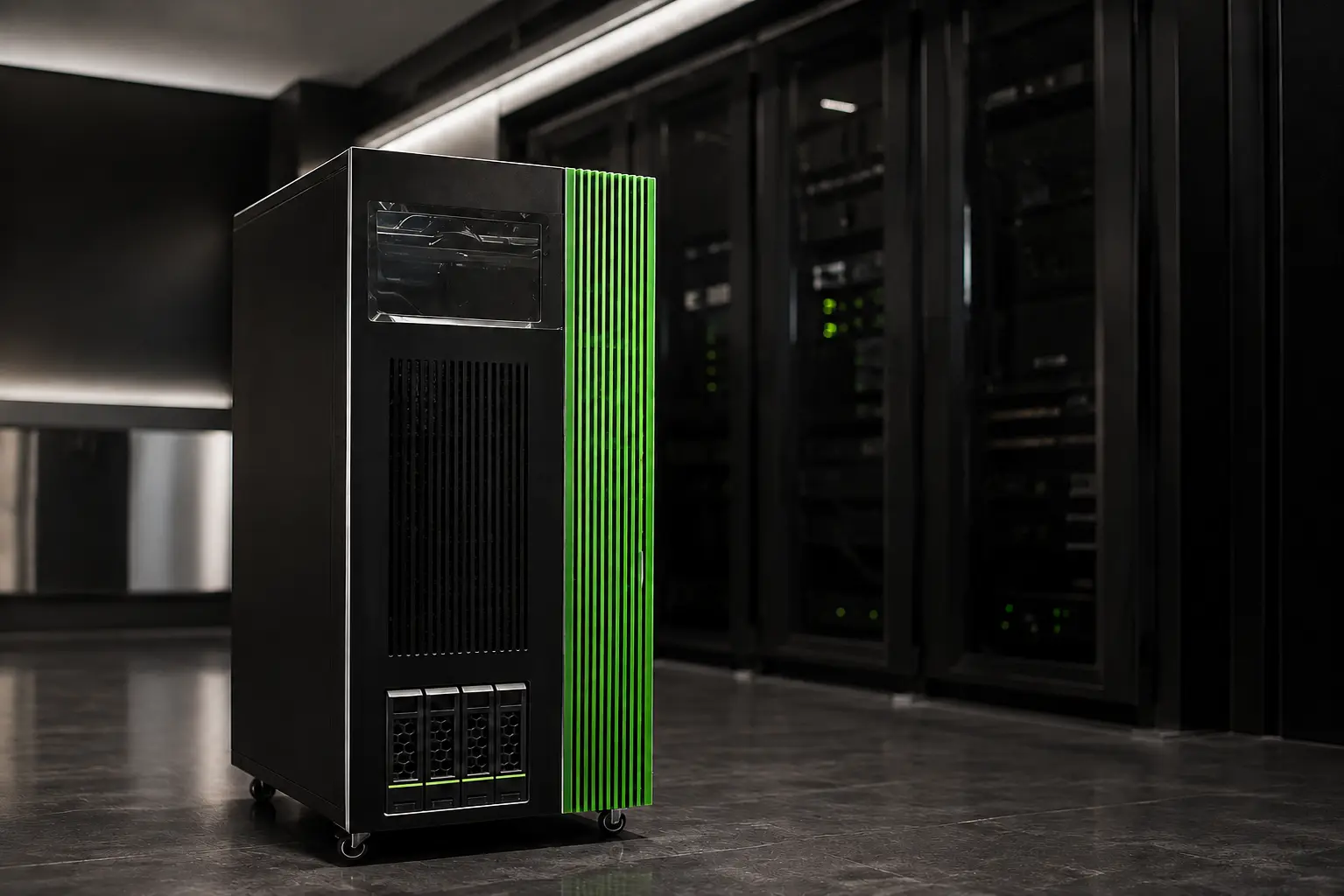
GRIFO 32 · 32 GPUs per module · scale up to 128 — GRIFOTTO · 8 GPUs · available now

BILLI DYNAMICS · GRIFO ARCHITECTURE · EUROPEAN DEEP TECH

INSIDE GRIFO 32

32–128 GPUs.

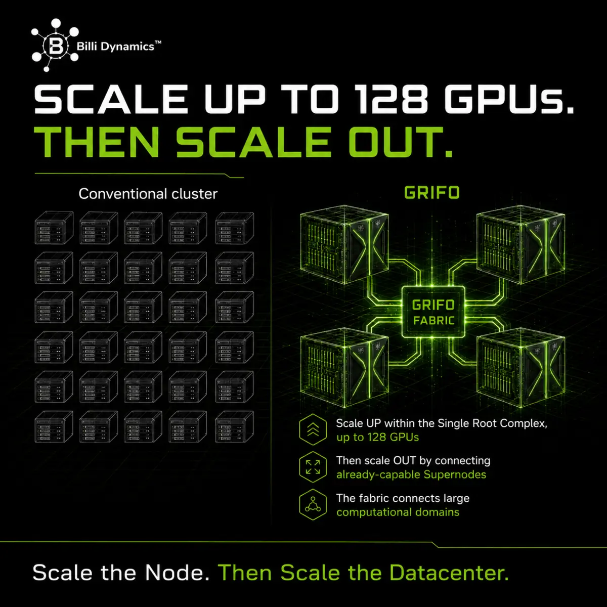
Scale up within a single root complex.

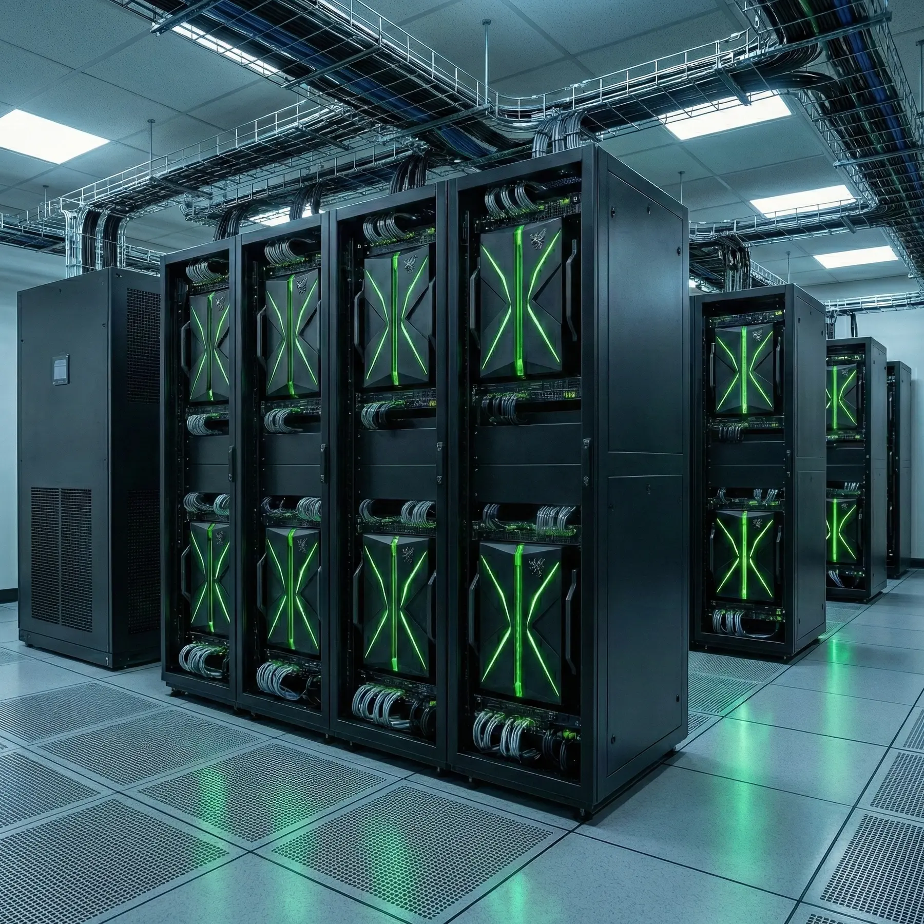
The core remains the GRIFO 32 module, with 32 GPUs. By connecting up to four modules through the PCIe fabric, the architecture scales to 128 GPUs within a single root complex: multiple physical modules, one coordinated PCIe domain.

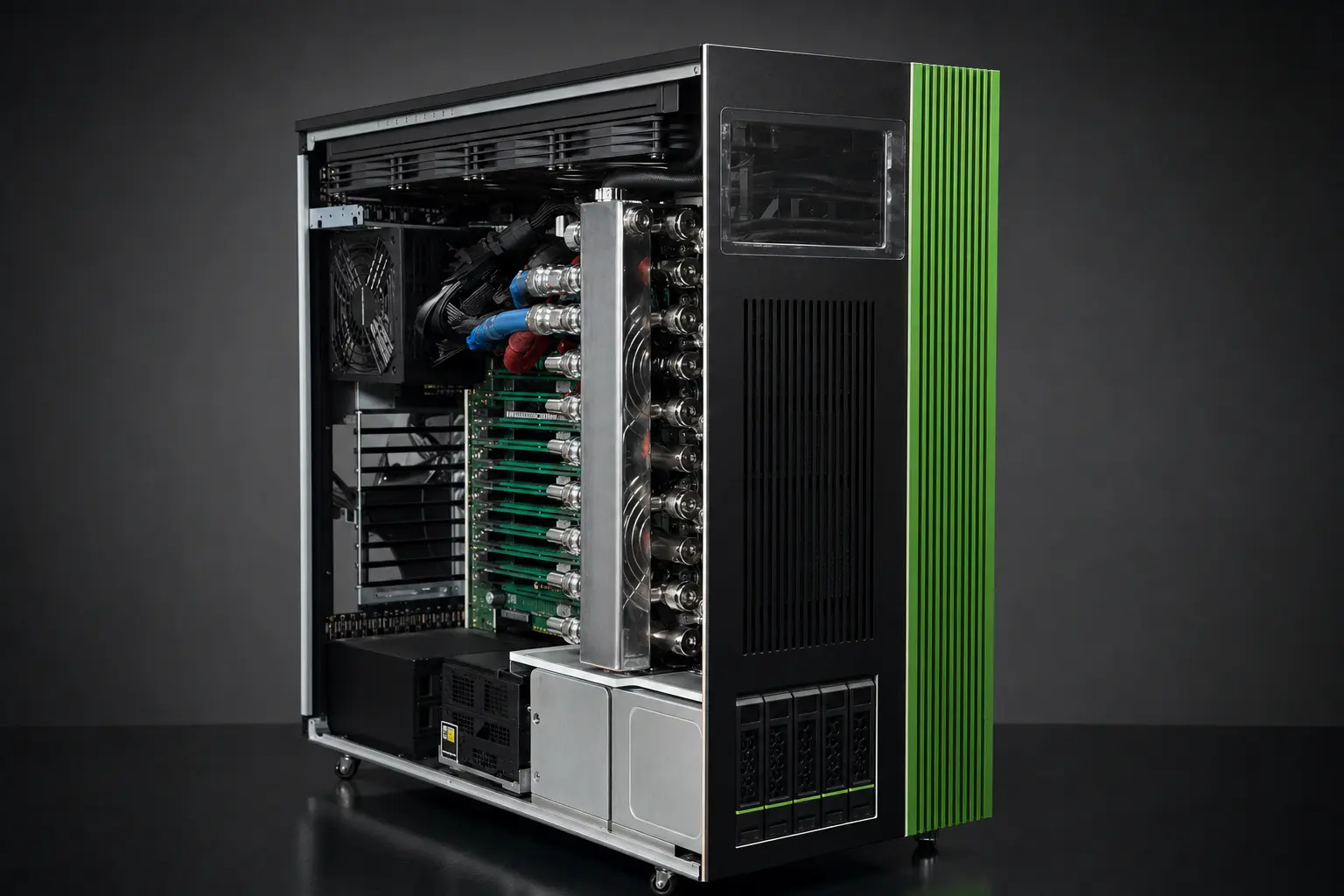
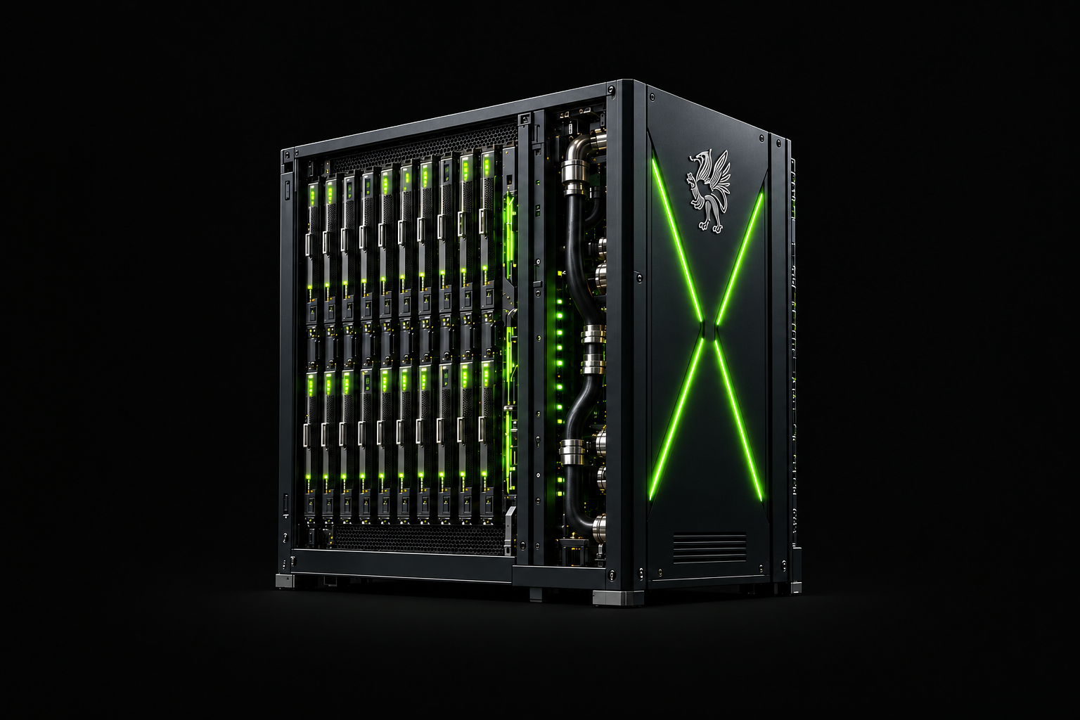
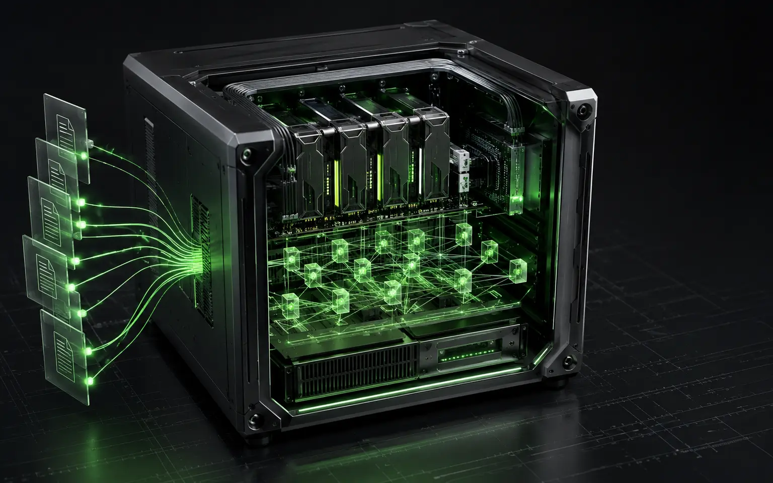
Photographic rendering of the open GRIFO 32: accelerators and cooling circuit inside the chassis
GRIFO 32 · Internal view · Photographic renderingDesigned by Billi Dynamics · System Architect: Emilio Billi

GRIFO, explained simply

One larger computer. Not a room full of computers.

GRIFO is a proprietary ecosystem of technologies designed by Billi Dynamics. Fabric, control, power and cooling keep accelerators working together, while qualified accelerators and I/O peripherals remain open to vendor choice.

Choose the right system

GRIFOTTO or GRIFO 32?

Choose by workload, required scale and installation conditions. GRIFOTTO brings eight accelerators into one complete machine; GRIFO 32 starts with a 32-accelerator module and extends the local domain through its PCIe fabric.

TWO DIFFERENT ROLES
08

Complete machine

GRIFOTTOA self-contained 8-accelerator system that can be configured and ordered now.
32

Modular scale-up ecosystem

GRIFO 3232 GPUs per core module. Up to four modules linked by PCIe fabric within one root complex.
LayerGRIFOTTOGRIFO 32
01System identityComplete systemA self-contained machine ready to host the workload.Modular supernode ecosystemFabric, power, thermals and control are designed together; qualified accelerators and I/O remain selectable.
02Local accelerator domain8 Gen5 x16 GPU positionsA dual-socket, dual-root NUMA domain.32 accelerators per module · up to 128 GPUsUp to four GRIFO 32 modules connected through PCIe fabric within one root complex.
03FabricDedicated Gen5 x16 connectionsInternal PCIe paths defined and validated at machine level.Single-root switched PCIe Gen5 fabricConnects accelerators within each module and extends the shared PCIe domain between modules.
04Scale-out network1 × 400G-ready NIC/HCA positionConnects storage or external infrastructure according to the deployment.Scale up locally, then scale outAdditional high-speed NICs/HCAs connect already-capable supernodes, storage and the data centre.
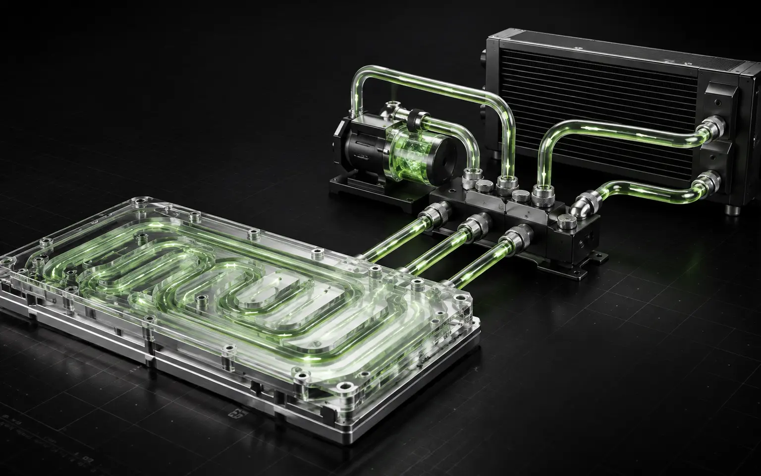
05Cooling architectureFull-system liquid coolingCPU, accelerators and critical components are managed inside the same machine.Three-layer thermal architectureCold plates, distribution/CDU and facility heat rejection are sized with the domain.
06Power architectureIntegrated machine power distributionConfigured around the number and envelope of the installed accelerators.Domain-level power deliveryDistribution, protection, cabling and thermal load are coordinated across the ecosystem.
07System controlBMC, firmware and topology validationComplete operational control of the individual system.Coordinated domain controlEnumeration, switching, firmware, telemetry and validation span every subsystem.
08Deployment modelA standalone machine or cluster nodeFor labs, AI/HPC, simulation and compact deployments.A data-centre building blockEnlarge the local machine first; then connect complete GRIFO domains at infrastructure scale.
09StatusConfigurable and orderable nowA documented reference system undergoing real validation.Flagship architectureIndustrialisation and validation of the 32-accelerator domain.
“Start with 32 GPUs. Connect up to four GRIFO 32 modules through PCIe fabric. Scale to 128 GPUs within one root complex.”
01

The definition

From accelerator to cooling loop, every part has a role in the same computing system.

01The PCIe fabric connects accelerators and GRIFO 32 modules into a shared local domain. Pooling, I/O management and communication topology define how resources are reached and coordinated.

02Power delivery and full-system liquid cooling are designed alongside that data path. High-performance networking provides the scale-out connections to storage and other computing domains.

02Billi Dynamics proprietary technology stack
01Single-root PCIe fabric02GPU pooling03High-performance networking04Optimised communication topologies
05Scale-out paths06Advanced I/O management07Power architecture08Full-system liquid cooling
03

Properties a conventional server does not possess

01High accelerator density
02Ultra-low-latency GPU-to-GPU communication
03Shared PCIe domain
04Direct access to resources
05Fewer inter-node bottlenecks
06Continuity from scale-up to scale-out
04 · SYSTEM DESIGN · DEVICE CHOICE

Agnostic only for accelerators and I/O

Select qualified accelerators and I/O peripherals for the workload, software stack and procurement requirements. The GRIFO system architecture provides continuity as those device choices evolve.

BILLI DYNAMICS CORE · QUALIFIED ACCELERATORS + I/O

FROM NETWORKED SERVERS TO ONE COORDINATED DOMAIN

Many separate machines
01 · NETWORKED SERVERS
Conventional data centre

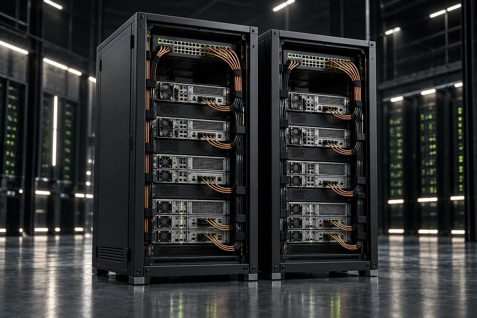
Every server has its own boundary. Data must repeatedly cross an external packet network.

Independent hosts · external network between nodes
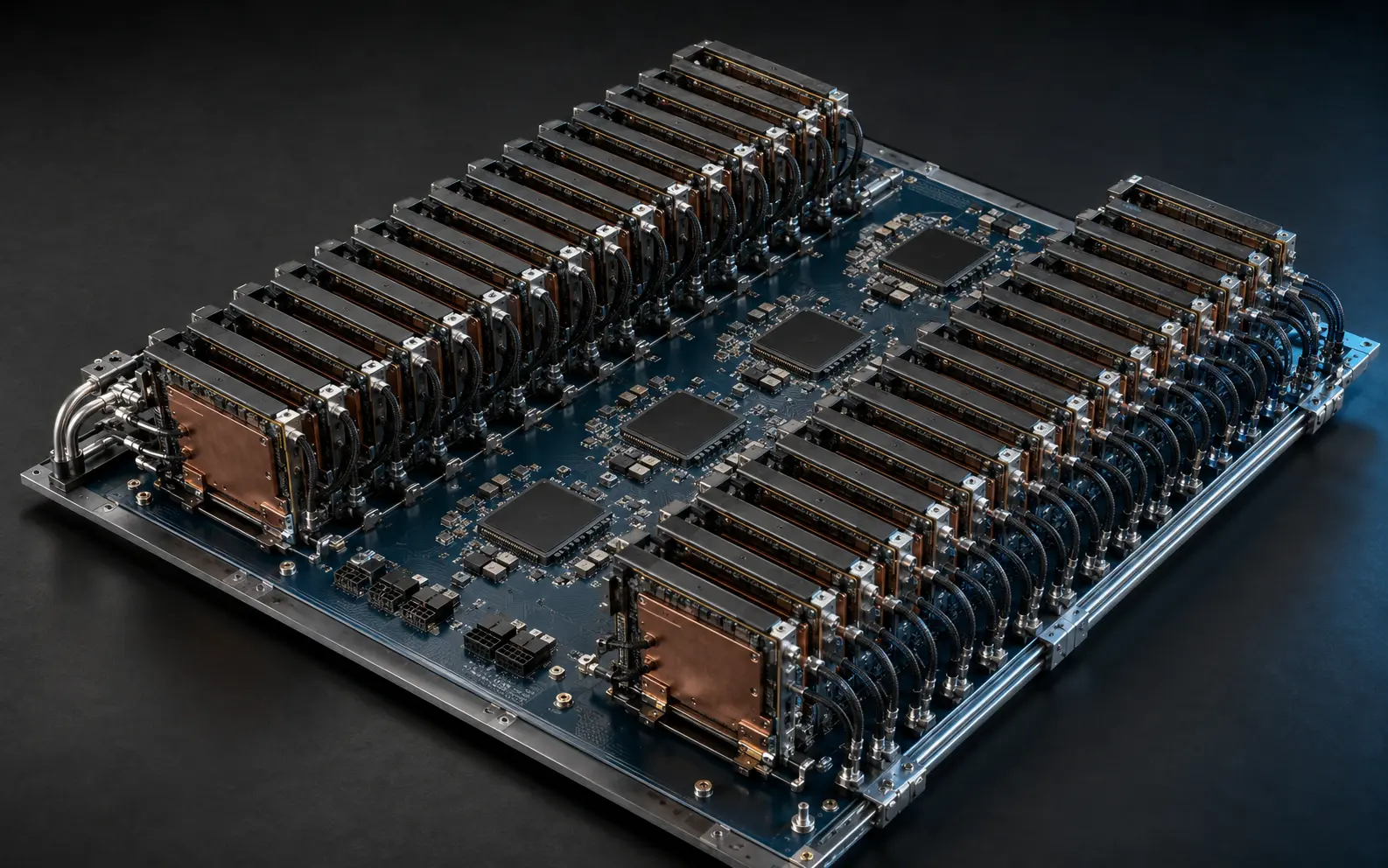
GRIFO 32: internal view of a single 32-GPU module
02 · ONE COORDINATED DOMAIN
GRIFO local domain

Accelerators, fabric and control are engineered as parts of one larger local machine.

32-GPU module · up to 128 GPUs by linking four modules through the PCIe fabric

Illustrative renderings: networked servers on the left, a single GRIFO 32 module on the right. The equal-accelerator comparison follows in the next section.

01

What changes?

Accelerators stop behaving like isolated resources in separate servers and become parts of one coordinated computing domain.

02

Why is it a supernode?

Because compute, memory, fabric, control, power and cooling are designed as parts of one machine.

03

Why is it needed now?

AI is increasingly limited by data distance, energy and heat — not only by the speed of the chips.

The future does not simply need more GPUs. It needs a machine capable of making them work together.

As models and datasets grow, moving data between isolated servers becomes more expensive. The architectural direction is therefore unavoidable: enlarge the useful local machine before scaling out across the data centre.

Architecture study · 128-accelerator reference scenario

Same accelerator count. A radically different infrastructure.

The study gives the conventional cluster 15.6% more theoretical compute. Then it follows what the data must cross before that compute can become useful work.

128 = 128128 H200 accelerators in each architecture

A deliberately conservative starting point

Both reference systems contain 128 NVIDIA H200 accelerators, using the form-factor and power variants stated in the study. The comparison assumes an idealised, perfectly tuned 1:1 fat-tree for the cluster and makes no claim that peak FLOPS equal application performance.
Conventional data centre
Across machines

16 independent compute nodes

16 nodes × 8 GPUs = 128 GPUs

Independent hosts · external network between nodes

Four GRIFO 32 modules · PCIe fabric · one root complex
Inside GRIFO

One coordinated 128-accelerator domain

4 modules × 32 GPUs = 128 GPUs

Four GRIFO 32 modules · PCIe fabric · one root complex

Illustrative architecture renderings. The comparison uses the configurations stated above; the number of units pictured is not a literal representation of the study topology.

Study parameterConventional data centreGRIFO
THEORETICAL COMPUTEConventional data centre126.6 PFLOPSGRIFO106.9 PFLOPS
MODELED COMMUNICATION PATHConventional data centre≥850 ns physical floorGRIFO≈505 ns switched local path
INFRASTRUCTURE IN THE LOCAL PATHConventional data centreNICs · optics · InfiniBand switchesGRIFOPCIe Gen5 fabric · no external packet boundary

Follow one exchange

MODELED COMMUNICATION PATH

Across machines

  1. 01PCIe DMA
  2. 02RDMA stack
  3. 03NIC
  4. 04optics
  5. 05IB switch
  6. 06destination copy

≥850 ns physical floor

Inside GRIFO

  1. 01PCIe port
  2. 02local switches
  3. 03PCIe port

≈505 ns switched local path

01

The path becomes shorter

The reference model places GRIFO’s local switched path at about 505 ns, compared with a conventional network path whose physical components alone total at least 850 ns.

02

Fewer boundaries consume the budget

The local exchange no longer needs to be serialised through a NIC, converted to an optical link, switched as a network packet and reconstructed at another server.

03

Peak becomes a system question

A component advantage on paper can be overtaken by time spent moving and coordinating data. The complete architecture determines how much compute reaches the workload.

“Peak compute is the starting number. Boundaries decide how much reaches the workload.”
STUDY MODEL — NOT AN APPLICATION BENCHMARK

Figures are derived from the stated 128-accelerator analytical reference model. They are not measured GRIFO 32 application results. Actual performance depends on the exact accelerator, topology, software stack and workload.

Business case · 8,192-GPU iso-topology

What changes at 8,192 GPUs? The five-year economics.

This analytical case compares 256 GRIFO 32 modules with 1,024 conventional 8-GPU nodes. Both contain 8,192 GPUs; each node has 8 × 400G uplinks. The estimates below apply to this specific infrastructure and operating scenario.

8,192One comparable 8,192-GPU case
018,192

H200 accelerators in both architectures

02256

GRIFO 32 domains · 32 GPUs each

031,024

conventional DGX nodes · 8 GPUs each

048 × 400G

uplinks per node · non-blocking fat-tree

01 · CAPEX≈ €95M

lower at the midpoint of the published estimate ranges

€400–485M conventional · €305–390M GRIFO 32
02 · OPEX · 5 YEARS≈ €76M

lower across energy, MRO, people and spares

€132M conventional · €56M GRIFO 32
03 · TCO · 5 YEARS≈ €171M

lower at the same 8,192-GPU scale

≈30% below the conventional cluster model
PROPORTIONAL TCO ADVANTAGE

More GRIFO. More absolute value retained.

The curve applies the published 8,192-GPU TCO result proportionally to the deployment checkpoints. It shows the economic effect accumulating as GRIFO replaces more conventional server boundaries; intermediate values are interpolation, not independent quotations.

GRIFO 32 units · equivalent GPU scaleEstimated cumulative advantage
CAPEX + OPEX

Where the five-year advantage comes from

The model separates the capital needed to build the infrastructure from the operating cost required to keep it running.

Conventional clusterGRIFO 32
CAPEX
€400–485M
€305–390M
OPEX · 5 YEARS
≈ €132M
≈ €56M
TOTAL TCO
€532–617M
€361–446M
PHYSICS → OPEX

The OPEX engine is physical

0115.58 → 6.74 MW

wall power at 8,192 GPUs

02387 GWh

energy avoided over five years

03€58.1M

energy cost avoided at €0.15/kWh

Planning a smaller deployment?

Start with the same cost categories: hosts, NICs, switches, optics, power and cooling. For one or a few machines, the advantage must be calculated for the actual configuration and utilisation. The 8,192-GPU case illustrates the effect at scale; it does not determine your project's savings.

“The value accumulates as more repeated server infrastructure is consolidated.”
ANALYTICAL BUSINESS CASE — NOT A COMMERCIAL QUOTE

Source: GRIFO 32 Cluster 8,192 GPU — Business Edition Rev. 1.1, April 2026. Figures are order-of-magnitude estimates for the stated NVIDIA H200 iso-topological reference case, 24/7 full load, €0.15/kWh and a five-year horizon. CAPEX benefit uses the midpoint of the published ranges; intermediate scale values are proportional interpolation. Actual costs depend on configuration, workload, procurement, facility, utilisation and energy price.
Software platforms

Turn compute into applications.

Choose the tools for your data, models and business processes.

02Software platforms
01

GPU-native data and AI execution

GRIFO DATA ENGINE

Move computation to the data instead of moving data through layers of infrastructure. GRIFO Data Engine brings relational, vector and AI-assisted operations closer to accelerator memory, turning large working sets into faster, more efficient decisions.

Best forLarge analytical working sets, vector search and AI-fused enterprise data.

Business advantages

  • Less movement between CPU and accelerators
  • One path for relational, vector and AI operations
  • Validation built around real customer queries
Request more information
GRIFO DATA ENGINE — GPU-native data and AI execution
Modelled and derivedTechnical architecture and workload validation
02

Private enterprise AI

CONFIDENTIALGPT

Turn confidential archives into usable institutional intelligence—inside your security perimeter. ConfidentialGPT helps teams find evidence, compare documents, reveal inconsistencies and prepare decisions without exporting sensitive knowledge to an external cloud.

Best forLegal, finance, public sector, research and organisations handling sensitive knowledge.

Business advantages

  • Sensitive knowledge stays local or air-gapped
  • Answers grounded in controlled documents and relationships
  • Faster research, comparison, dossiers and workflows
Request more information
CONFIDENTIALGPT — Private enterprise AI
Development platformAdvanced development; availability on request
03

Predictive intelligence

PROFETA

Move from reports that describe the past to scenarios that illuminate the next decision. PROFETA combines forecasting, simulation and operational context so organisations can test alternatives before their consequences become costs.

Best forEnergy, manufacturing, operations and planning teams.

Business advantages

  • Anticipate demand, risk and operational change
  • Compare alternative scenarios before acting
  • Connect forecasts to real decision workflows
Request more information
PROFETA — Predictive intelligence
Development platformSolution development
04

Visual and signal intelligence

iVST

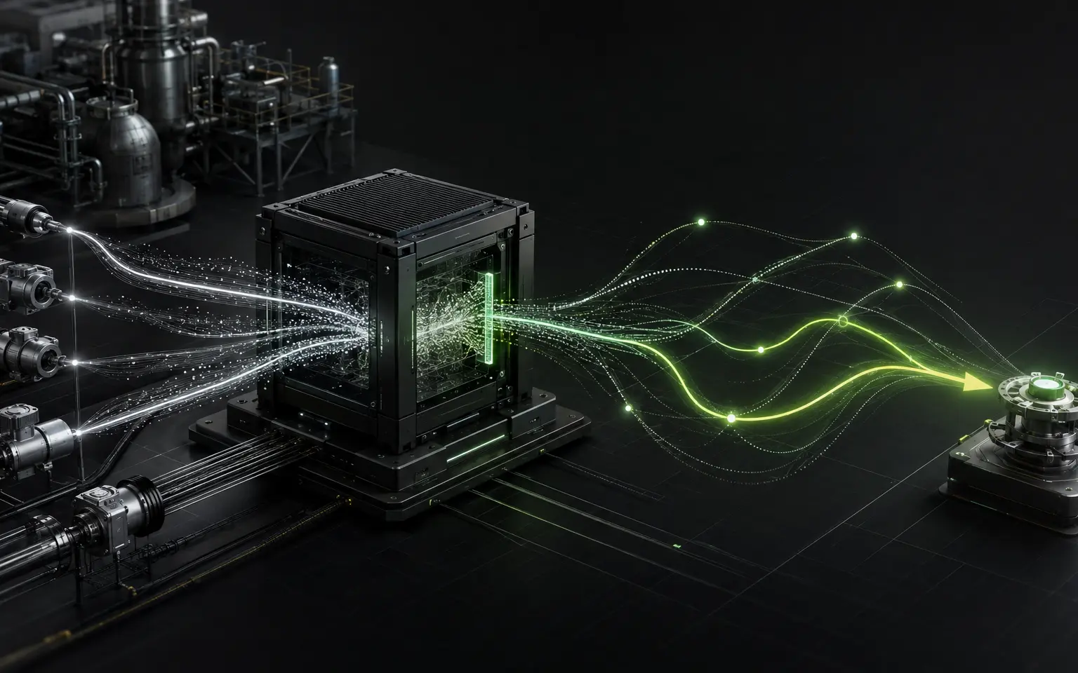
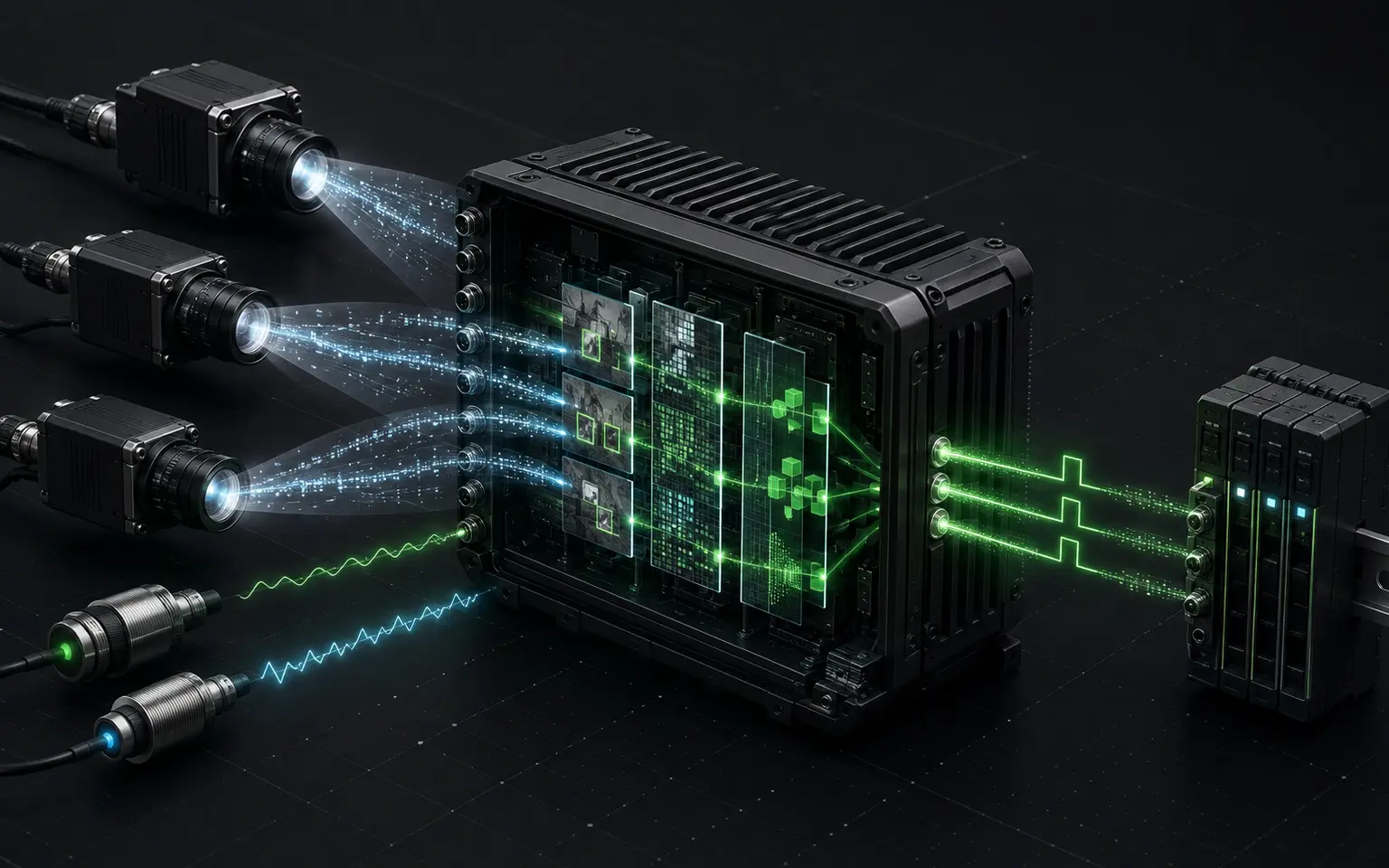
Give operational systems eyes and ears. iVST converts video, images and complex sensor signals into correlated events that inspection, security and automation systems can understand and act upon.

Best forIndustrial inspection, multi-camera analytics, security and autonomous systems.

Business advantages

  • One interpretation layer across cameras and signals
  • From raw streams to actionable operational events
  • Edge-to-system integration for real environments
Request more information
iVST — Visual and signal intelligence
Development platformSolution development and project validation
03Engineering capability

Why architecture matters

Peak components do not guarantee useful performance.

A peak specification describes what one component could do under ideal conditions. Real work finishes only when data reaches the accelerators, memory keeps them fed, the fabric coordinates them, software uses them efficiently, and power and cooling sustain the machine for the entire run.

COMPONENT PROMISETHEORETICAL PEAK

What the accelerator could compute when every supporting condition is ideal.

A NUMBER ON A SPEC SHEET
THE PATH EVERY WORKLOAD MUST CROSS01—06
01Workload
02Data locality
03Memory
04Fabric
05Software
06Power + cooling
SYSTEM OUTCOMEUSEFUL PERFORMANCE

How much correct work the complete system actually finishes per unit of time, energy and cost.

A MEASURABLE RESULT
THE ARCHITECTURAL RULE
The slowest necessary passage sets the pace for the whole system.

If data, memory, fabric, software or cooling slows down, the accelerators wait. Adding more peak compute does not remove that waiting time; the complete path must be redesigned.

PEAK ≠ RESULT · THE NARROWEST RELEVANT CUT GOVERNS
01
Workload

The machine must match the model, precision, batch size and required time-to-result.

02
Data locality

Data must already be close to the compute instead of waiting beyond distant server boundaries.

03
Memory

Capacity keeps the problem resident; bandwidth feeds accelerators at the rate they consume.

04
Fabric

Every exchange and synchronisation needs enough bandwidth, low enough latency and predictable behaviour.

05
Software

Drivers, runtimes and scheduling must expose the hardware as one coordinated system.

06
Power + cooling

The facility must sustain clocks and density for the entire run, not only for a short burst.

Documented evidence

Specifications, system validation and measured results.

Reference configurations and validation scope are stated separately from analytical studies.

01 · DOCUMENTED SPECIFICATION

GRIFOTTO reference system

8 Gen5 x16 GPU positions · dual Xeon reference compute · 2 TB reference memory · 400G-ready I/O

02 · ARCHITECTURE SPECIFICATION

GRIFO 32 architecture

Up to 32 full-length PCIe accelerators · one single-root Gen5 switched fabric · liquid cooling by design

03 · VALIDATION PLAN

Validation protocol

Power · firmware · BMC · GPU/PCIe/NUMA topology · network and GPUDirect checks

BENCHMARK POLICYApplication benchmark results will be published only with the exact configuration, workload, software versions and measurement conditions.

Solutions

Begin with the problem, not the parts list.

We define the workload, data path, facility boundary and success criteria before configuring the machine.

01

Private and sovereign AI

Knowledge, models and workflows under direct organisational control.

CONFIDENTIALGPT + GRIFO
02

High-density AI

More accelerators in a local domain, with thermals and facility designed together.

GRIFO 32
03

Scientific computing

Simulation, accelerated analytics and AI in a workload-oriented system.

GRIFOTTO + GRIFO
04

GPU-native analytics

Relational, vector and AI operations closer to accelerator memory.

GRIFO DATA ENGINE
Emilio Billi, Founder, CTO and System Architect

Founder & System Architect

Emilio Billi — the architect behind GRIFO.

For more than twenty years, between Europe and the United States, Emilio Billi has worked on HPC, PCIe scale-up, shared memory, accelerated systems and hardware-software co-design. His method starts from the path of data and turns physical limits into design decisions.

“The system is the product. Measurement is the proof.”
01 · Model02 · Numbers03 · Measurement04 · Decision
AI Infrastructure senza nebbia — Emilio Billi

SELECTED WORK · 2026

AI Infrastructure
senza nebbia
Read the full profile and body of work

Company

A founder-led European deep-tech company.

Billi Dynamics S.r.l. turns system architecture into industrial products for AI, scientific computing, analytics and mission-critical deployments.

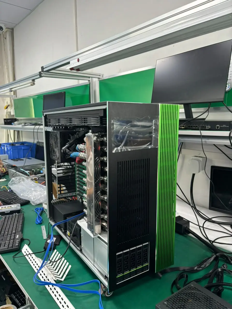
GRIFOTTO laboratory assembly

ENGINEERING PROOFReal system assembly and validation in the Billi Dynamics laboratory.

Leadership and board

Emilio Billi

Emilio Billi

Founder & CTO (acting CEO)

Deep-tech entrepreneur and system architect with more than 20 years across HPC, AI infrastructure and hardware-software co-design.
01
Pietro Camasta

Pietro Camasta

BizOps

Connects business operations, strategy and execution to support controlled scale-up.
02
P.F. Girard

P.F. Girard

Board Member

Industrial leader with experience in innovation, digitalisation, operational excellence and growth.
03
Christopher Shelton-Agar

Christopher Shelton-Agar

CSO

Commercial and strategy leader for positioning, alliances and revenue-focused growth.
04

Start with your workload

Tell us what the machine must accomplish.

Tell us about your application and the scale you need. The first technical conversation helps define a suitable configuration, installation requirements and the validation path for your workload.

  1. Application and goal

    Define your data, models, capacity and time-to-result requirements.

  2. Configuration and facility

    Review the system, accelerators, I/O, power and cooling requirements.

  3. Validation and support scope

    Agree which tests are needed and the installation, commissioning and support scope to include in the proposal.

MODEL · NUMBERS · MEASUREMENT · DECISION

This form prepares an email in your email application. Send that message to complete your request.